logo
Contact Us

source-code

NebulaGraph Source Code Explained: Planner

NebulaGraph Source Code Explained: Planner

In the last article, we mentioned that Validator will convert an AST generated by Parser to an execution plan. In this article, we will explain how an execution plan is generated.

Overview  

NebulaGraph Source Code Explained: Planner

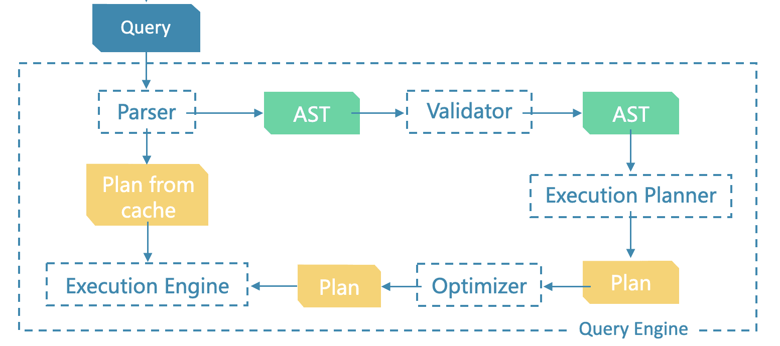
Planner is an execution plan generator. It generates an execution plan based on the semantically valid AST that was validated by Validator, and then passes the plan to Optimizer to generate an optimized execution plan. Finally, Executor will execute the optimized plan. An execution plan is composed of a series of nodes (PlanNode).

Structure of Source Files

Here is the structure of source files for Planner.  

src/planner
├── CMakeLists.txt
├── match/
├── ngql/
├── plan/
├── Planner.cpp
├── Planner.h
├── PlannersRegister.cpp
├── PlannersRegister.h
├── SequentialPlanner.cpp
├── SequentialPlanner.h
└── test

The Planner.h file defines the data structure of SubPlan and the interfaces of Planner.

struct SubPlan {
    // root and tail of a subplan.
    PlanNode*   root{nullptr};
    PlanNode*   tail{nullptr};
};

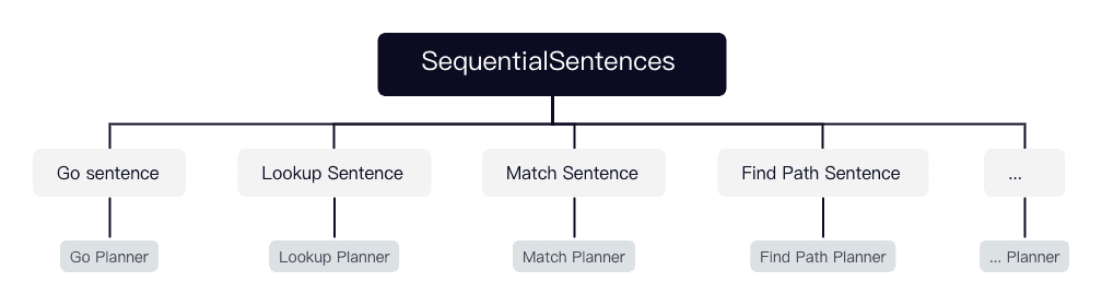
PlannersRegister is responsible for registering available planners. So far, SequentialPlanner, PathPlanner, LookupPlanner, GoPlanner, and MatchPlanner have been registered for NebulaGraph.

The corresponding sentence of SequentialPlanner is SequentialSentences, which is a combined sentence composed of multiple sentences separated with semicolons. Each sentence can be a GO, LOOKUP, or MATCHstatement. Therefore, SequentialPlanner generates multiple execution plans by calling other sentence planners and then calling Validator::appendPlan to connect the plans end to end.

NebulaGraph Source Code Explained: Planner

The match/ directory defines the planners and connection strategies of SubPlans of some statements and clauses compatible with openCypher, such as MATCH, UNWIND, WITH, RETURN, WHERE, ORDER BY, SKIP, and LIMIT. SegmentsConnector uses an appropriate strategy, such as AddInput, addDependency, or innerJoinSegments, to connect the SubPlans end to end to generate a complete execution plan.

src/planner/match
├── AddDependencyStrategy.cpp
├── AddDependencyStrategy.h
├── AddInputStrategy.cpp
├── AddInputStrategy.h
├── CartesianProductStrategy.cpp
├── CartesianProductStrategy.h
├── CypherClausePlanner.h
├── EdgeIndexSeek.h
├── Expand.cpp
├── Expand.h
├── InnerJoinStrategy.cpp
├── InnerJoinStrategy.h
├── LabelIndexSeek.cpp
├── LabelIndexSeek.h
├── LeftOuterJoinStrategy.h
├── MatchClausePlanner.cpp
├── MatchClausePlanner.h
├── MatchPlanner.cpp
├── MatchPlanner.h
├── MatchSolver.cpp
├── MatchSolver.h
├── OrderByClausePlanner.cpp
├── OrderByClausePlanner.h
├── PaginationPlanner.cpp
├── PaginationPlanner.h
├── PropIndexSeek.cpp
├── PropIndexSeek.h
├── ReturnClausePlanner.cpp
├── ReturnClausePlanner.h
├── SegmentsConnector.cpp
├── SegmentsConnector.h
├── SegmentsConnectStrategy.h
├── StartVidFinder.cpp
├── StartVidFinder.h
├── UnionStrategy.h
├── UnwindClausePlanner.cpp
├── UnwindClausePlanner.h
├── VertexIdSeek.cpp
├── VertexIdSeek.h
├── WhereClausePlanner.cpp
├── WhereClausePlanner.h
├── WithClausePlanner.cpp
├── WithClausePlanner.h
├── YieldClausePlanner.cpp
└── YieldClausePlanner.h

The ngql/ directory defines the planners of nGQL statements such as GO, LOOKUP, and FIND PATH.

src/planner/ngql
├── GoPlanner.cpp
├── GoPlanner.h
├── LookupPlanner.cpp
├── LookupPlanner.h
├── PathPlanner.cpp
└── PathPlanner.h

The plan/ directory defines seven categories, with a total of more than 100 plan nodes.

src/planner/plan
├── Admin.cpp
├── Admin.h
├── Algo.cpp
├── Algo.h
├── ExecutionPlan.cpp
├── ExecutionPlan.h
├── Logic.cpp
├── Logic.h
├── Maintain.cpp
├── Maintain.h
├── Mutate.cpp
├── Mutate.h
├── PlanNode.cpp
├── PlanNode.h
├── Query.cpp
├── Query.h
└── Scan.h

Here is an introduction to the purpose of plan nodes:

  • Admin: For the nodes related to database administration.
  • Algo: For the nodes related to the algorithms of paths, subgraphs, and so on.
  • Logic: For the nodes related to logic controlling, such as loop and binary selection.
  • Maintain: For the nodes related to schema.
  • Mutate: For the nodes related to DML.
  • Query: For the nodes related to query computation.
  • Scan: For the nodes related to indexing and scanning.

In the Executor phase, each PlanNode generates an executor, and each executor is responsible for a specific functionality.

For example, here is the source code of the GetNeighbors node.

static GetNeighbors* make(QueryContext* qctx,
                              PlanNode* input,
                              GraphSpaceID space,
                              Expression* src,
                              std::vector<EdgeType> edgeTypes,
                              Direction edgeDirection,
                              std::unique_ptr<std::vector<VertexProp>>&& vertexProps,
                              std::unique_ptr<std::vector<EdgeProp>>&& edgeProps,
                              std::unique_ptr<std::vector<StatProp>>&& statProps,
                              std::unique_ptr<std::vector<Expr>>&& exprs,
                              bool dedup = false,
                              bool random = false,
                              std::vector<storage::cpp2::OrderBy> orderBy = {},
                              int64_t limit = -1,
                              std::string filter = "")

GetNeighbors is the semantic encapsulation of the KV of an edge in the storage layer. Based on the source vertex of the given edge type, it will find the destination vertex of an edge. During the finding edge course, GetNeighbors can retrieve the properties of the edge (edgeProps). Additionally, the outgoing edge is stored with its source vertex in one partition (shard), so the properties of the source vertex (vertexProps) can be retrieved easily.

Here is the source code of the Aggregate node.

static Aggregate* make(QueryContext* qctx,
                               PlanNode* input, 
                               std::vector<Expression*>&& groupKeys = {},
                               std::vector<Expression*>&& groupItems = {})

The Aggregate node is for aggregate computing. It groups the table according to groupKeys, and does aggregate calculation on groupItems.

Here is the source code of the Loop node.

static Loop* make(QueryContext* qctx,
                      PlanNode* input,
                      PlanNode* body = nullptr,
                      Expression* condition = nullptr);

The Loop node is for looping. It keeps on executing the PlanNode segement between the body and the next Start node until the value of condition is changed to false.

Here is the source code of the InnerJoin node.

static InnerJoin* make(QueryContext* qctx,
                           PlanNode* input,
                           std::pair<std::string, int64_t> leftVar,
                           std::pair<std::string, int64_t> rightVar,
                           std::vector<Expression*> hashKeys = {},
                           std::vector<Expression*> probeKeys = {})

The InnerJoin node aims to perform inner join between two tables (Table or DataSet). leftVar and rightVar refer to the two tables respectively.

Entry Functions

The entry function of Planner is Validator∷toPlan().

Status Validator::toPlan() {
    auto* astCtx = getAstContext();
    if (astCtx != nullptr) {
        astCtx->space = space_;
    }
    auto subPlanStatus = Planner::toPlan(astCtx);
    NG_RETURN_IF_ERROR(subPlanStatus);
    auto subPlan = std::move(subPlanStatus).value();
    root_ = subPlan.root;
    tail_ = subPlan.tail;
    VLOG(1) << "root: " << root_->kind() << " tail: " << tail_->kind();
    return Status::OK();
}

Steps

1. Calling getAstContext()

Firstly, getAstContext() is called to obtain the validated (by Validator) and rewritten AST contexts. The data structure of these contexts are defined in src/context/.

src/context/ast
├── AstContext.h
├── CypherAstContext.h
└── QueryAstContext.h
struct AstContext {
    QueryContext*   qctx; // The context of each query request
    Sentence*       sentence; // The AST of each query statement
    SpaceInfo       space; // The current graph space
};

CypherAstContext defines the AST contexts of the openCypher compatible statements. QueryAstContext defines the AST contexts of the nGQL statements.

2.Calling Planner::toPlan(astCtx)

Secondly, Planner∷toPlan(astCtx) is called. Based on the AST contexts, it will find the registered planners for the query statement in PlannerMap, and then the corresponding execution plan is generated.

Each plan is composed of a series of PlanNodes. There are two major relationships between PlanNodes, execution dependency and data dependency.

  1. Execution dependency: From the perspective of execution order, an execution plan is a directed acyclic graph, and the dependencies between nodes are determined when the plan is generated. In the execution phase, the executor generates an operator for each node, and starts scheduling from the root node. If the root node is found dependent on another node, a recursive calling is executed for the node that the root node depends on. The process repeats until it finds a node that is not dependent on any other nodes. And then, the node is executed. After the execution is done, the executor will continue to execute the nodes that depend on it until the root node is reached.
  2. Data dependency: The data dependency between nodes is like the execution dependency, that is, the output of the previous execution is the input of the next execution. Let's take the InnerJoin node as an example. The inputs of InnerJoin may be the outputs of some nodes that are not adjacent to it.

NebulaGraph Source Code Explained: Planner

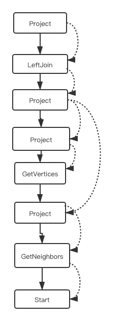
(In the preceding figure, the solid lines represent the execution dependencies and the dashed lines represent the data dependencies.)

An Example

In this section, I will take MatchPlanner as an example to show how an execution plan is generated.

Here is the example statement.

MATCH (v:player)-[:like*2..4]-(v2:player)\
WITH v, v2.age AS age ORDER BY age WHERE age > 18\
RETURN id(v), age

After validated by MatchValidator and rewritten, this statement will be output as a tree composed of contexts.

NebulaGraph Source Code Explained: Planner

=>

NebulaGraph Source Code Explained: Planner

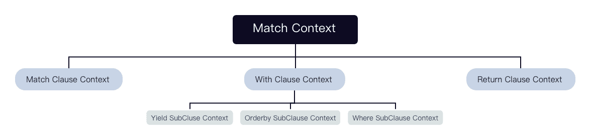
Each context corresponds to a clause or a subclause.

enum class CypherClauseKind : uint8_t {
    kMatch,
    kUnwind,
    kWith,
    kWhere,
    kReturn,
    kOrderBy,
    kPagination,
    kYield,
};

struct CypherClauseContextBase : AstContext {
    explicit CypherClauseContextBase(CypherClauseKind k) : kind(k) {}
    virtual ~CypherClauseContextBase() = default;

    const CypherClauseKind  kind;
};

struct MatchClauseContext final : CypherClauseContextBase {
    MatchClauseContext() : CypherClauseContextBase(CypherClauseKind::kMatch) {}

    std::vector<NodeInfo>                       nodeInfos; // The vertices involved in the pattern
    std::vector<EdgeInfo>                       edgeInfos; // The edges involved in the pattern
    PathBuildExpression*                        pathBuild{nullptr}; // Constructing the expression of Path
    std::unique_ptr<WhereClauseContext>         where; // filter SubClause
    std::unordered_map<std::string, AliasType>* aliasesUsed{nullptr}; // The specified alias
    std::unordered_map<std::string, AliasType>  aliasesGenerated; // The generated alias
};
...

And then, these steps are followed:

1.Finding Planner for the Statement

This is a MATCH statement, so MatchPlanner is found from the PlannerMap.

2.Generating a Plan

MatchPlanner::transform is called to generate an execution plan.

StatusOr<SubPlan> MatchPlanner::transform(AstContext* astCtx) {
    if (astCtx->sentence->kind() != Sentence::Kind::kMatch) {
        return Status::Error("Only MATCH is accepted for match planner.");
    }
    auto* matchCtx = static_cast<MatchAstContext*>(astCtx);

    std::vector<SubPlan> subplans;
    for (auto& clauseCtx : matchCtx->clauses) {
        switch (clauseCtx->kind) {
            case CypherClauseKind::kMatch: {
                auto subplan = std::make_unique<MatchClausePlanner>()->transform(clauseCtx.get());
                NG_RETURN_IF_ERROR(subplan);
                subplans.emplace_back(std::move(subplan).value());
                break;
            }
            case CypherClauseKind::kUnwind: {
                auto subplan = std::make_unique<UnwindClausePlanner>()->transform(clauseCtx.get());
                NG_RETURN_IF_ERROR(subplan);
                auto& unwind = subplan.value().root;
                std::vector<std::string> inputCols;
                if (!subplans.empty()) {
                    auto input = subplans.back().root;
                    auto cols = input->colNames();
                    for (auto col : cols) {
                        inputCols.emplace_back(col);
                    }
                }
                inputCols.emplace_back(unwind->colNames().front());
                unwind->setColNames(inputCols);
                subplans.emplace_back(std::move(subplan).value());
                break;
            }
            case CypherClauseKind::kWith: {
                auto subplan = std::make_unique<WithClausePlanner>()->transform(clauseCtx.get());
                NG_RETURN_IF_ERROR(subplan);
                subplans.emplace_back(std::move(subplan).value());
                break;
            }
            case CypherClauseKind::kReturn: {
                auto subplan = std::make_unique<ReturnClausePlanner>()->transform(clauseCtx.get());
                NG_RETURN_IF_ERROR(subplan);
                subplans.emplace_back(std::move(subplan).value());
                break;
            }
            default: { return Status::Error("Unsupported clause."); }
        }
    }

    auto finalPlan = connectSegments(astCtx, subplans, matchCtx->clauses);
    NG_RETURN_IF_ERROR(finalPlan);
    return std::move(finalPlan).value();
}

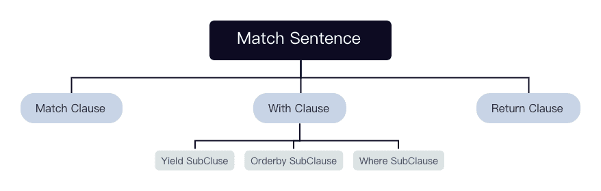
A MATCH statement may be composed of multiple MATCH, UNWIND, WITH, and RETURNclauses. Therefore, with MatchPlanner::transform, the corresponding ClausePlanners are called directly to generate the corresponding SubPlans, and then the SubPlans are connected end to end by SegmentsConnector according to the appropriate connection strategies.

In the example statement, the first clause is a MATCH clause: MATCH (v:player)-[:like*2..4]-(v2:player), so MatchClausePlanner::transform is called.

StatusOr<SubPlan> MatchClausePlanner::transform(CypherClauseContextBase* clauseCtx) {
    if (clauseCtx->kind != CypherClauseKind::kMatch) {
        return Status::Error("Not a valid context for MatchClausePlanner.");
    }

    auto* matchClauseCtx = static_cast<MatchClauseContext*>(clauseCtx);
    auto& nodeInfos = matchClauseCtx->nodeInfos;
    auto& edgeInfos = matchClauseCtx->edgeInfos;
    SubPlan matchClausePlan;
    size_t startIndex = 0;
    bool startFromEdge = false;

    NG_RETURN_IF_ERROR(findStarts(matchClauseCtx, startFromEdge, startIndex, matchClausePlan));
    NG_RETURN_IF_ERROR(
        expand(nodeInfos, edgeInfos, matchClauseCtx, startFromEdge, startIndex, matchClausePlan));
    NG_RETURN_IF_ERROR(projectColumnsBySymbols(matchClauseCtx, startIndex, matchClausePlan));
    NG_RETURN_IF_ERROR(appendFilterPlan(matchClauseCtx, matchClausePlan));
    return matchClausePlan;
}

The MatchClausePlanner::transform method performs these steps:

  1. Finding the starting vertex of the expansion.

Currently, three strategies are available for finding the starting vertex. They are registered in startVidFinders.

// MATCH(n) WHERE id(n) = value RETURN n
startVidFinders.emplace_back(&VertexIdSeek::make);

// MATCH(n:Tag{prop:value}) RETURN n
// MATCH(n:Tag) WHERE n.prop = value RETURN n
startVidFinders.emplace_back(&PropIndexSeek::make);

// seek by tag or edge(index)
// MATCH(n: tag) RETURN n
// MATCH(s)-[:edge]->(e) RETURN e
startVidFinders.emplace_back(&LabelIndexSeek::make);

Of these three strategies, VertexIdSeek is the best, which can locate the specific VID of the starting vertex. PropIndexSeek is the second, which is converted to an IndexScan that filters vertices by the property. LabelIndexSeek will be converted to an IndexScan.

For each strategy of finding the starting vertex, the findStarts function will traverse all the nodes in the MATCH pattern until it finds a node that can be used as the node of the starting vertex, and generates corresponding PlanNodes for finding the starting vertex.

For this example statement, LabelIndexScan is used and the starting vertex is v. Finally, an IndexScan node is generated and the indexes on the player tag are used.

  1. According to the starting vertex and the MATCH pattern, an expansion across multiple steps is executed.

For the example statement, the MATCH pattern is (v:player)-[:like*1..2]-(v2:player). It means v is the starting vertex, and an expansion across one or two steps along the like edge is executed, and the end vertex is of the player tag.

Here is how the expansion is executed.

Status Expand::doExpand(const NodeInfo& node, const EdgeInfo& edge, SubPlan* plan) {
    NG_RETURN_IF_ERROR(expandSteps(node, edge, plan));
    NG_RETURN_IF_ERROR(filterDatasetByPathLength(edge, plan->root, plan));
    return Status::OK();
}

An expansion across multiple steps will generate a Loop node. The body of the Loop node is expandStep , which means a one-step expansion is executed from the given starting vertex and such an expansion generates a GetNeighbors node. The end vertex of each expansion is the starting vertex of the next expansion. It keeps looping until the maximum number of steps specified in the pattern is reached.

To do the Step M expansion, the end vertex of the M-1 steps long path is used as the starting vertex of the expansion. By expanding one step more, the expansion result is constructed as a 1-step long path consisting of the source vertex of an edge and the edge itself. And then InnerJoin is performed to the 1-step long path and the previous M-1 steps long path to obtain a set of paths of M steps long.

This set of paths are filtered to remove the paths with duplicate edges, which are not allowed for path expansion in openCypher. Finally, the end vertex is used as the starting vertex of the next expansion. Such expansions continue until the specified maximum number of steps is reached.

After Loop, a UnionAllVersionVar node is generated. It combines the paths varying from 1-step to M-steps long that are generated from the execution of each loop of the body. The filterDatasetByPathLength() function will generate a Filter node to filter out all the paths that are shorter than the minimum number of steps specified in the MATCH pattern.

After the expansion, the path looks like (v)-like-()-e-(v)-?, where the properties of the end vertex is still missing. At this point, generating a GetVertices node is needed. When the end vertex is obtained, an InnerJoin is performed to it and the M-steps long path, and then we will have a set of paths that meet the requirements of the MATCH pattern.

More information about the expansion across multiple steps of MATCH will be introduced in a new article "Variable Length Pattern Match".

// Build Start node from first step
SubPlan loopBodyPlan;
PlanNode* startNode = StartNode::make(matchCtx_->qctx);
startNode->setOutputVar(firstStep->outputVar());
startNode->setColNames(firstStep->colNames());
loopBodyPlan.tail = startNode;
loopBodyPlan.root = startNode;

// Construct loop body
NG_RETURN_IF_ERROR(expandStep(edge,
                              startNode,                // dep
                              startNode->outputVar(),   // inputVar
                              nullptr,
                              &loopBodyPlan));

NG_RETURN_IF_ERROR(collectData(startNode,           // left join node
                               loopBodyPlan.root,   // right join node
                               &firstStep,          // passThrough
                               &subplan));
// Union node
auto body = subplan.root;

// Loop condition
auto condition = buildExpandCondition(body->outputVar(), startIndex, maxHop);

// Create loop
auto* loop = Loop::make(matchCtx_->qctx, firstStep, body, condition);

// Unionize the results of each expansion which are stored in the firstStep node
auto uResNode = UnionAllVersionVar::make(matchCtx_->qctx, loop);
uResNode->setInputVar(firstStep->outputVar());
uResNode->setColNames({kPathStr});

subplan.root = uResNode;
plan->root = subplan.root; 
  1. A table is output and its column names are determined.

All named symbols specified in the MATCH pattern are used as the column names to generate a table for the subsequent clauses, which will generate a Project node.

The second clause in the example statement is WITH. It calls WithClause::transform to generate SubPlans.

WITH v, v2.age AS age ORDER BY age WHERE age > 18

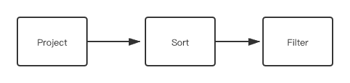
This WITH clause yields a table with two columns named v and v2.age. These columns are sorted by age, and then the table is used as a filter.

The YIELD part will generate a Project node. The ORDER BY part will generate a Sort node. And the WHERE part will generate a Filter node.

NebulaGraph Source Code Explained: Planner

The third clause is RETURN. It will generate a Project node.

RETURN id(v), age

The complete execution plan of the example statement is shown as follows.

NebulaGraph Source Code Explained: Planner

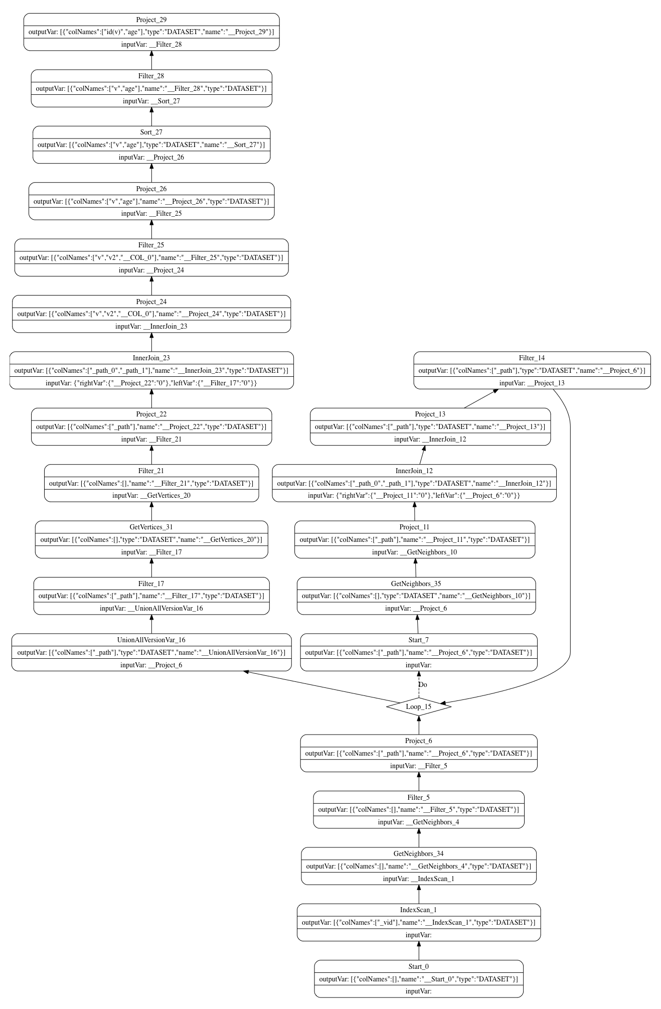
This is the end of this article.

If you encounter any problems in the process of using NebulaGraph, please refer to NebulaGraph Database Manual to troubleshoot the problem. It records in detail the knowledge points and specific usage of the graph database and the graph database NebulaGraph.

Join our Slack channel if you want to discuss with the rest of the NebulaGraph community!